• Husqvarna Motorcycles Made In Sweden - About 1988 and older

  • Hi everyone,

    As you all know, Coffee (Dean) passed away a couple of years ago. I am Dean's ex-wife's husband and happen to have spent my career in tech. Over the years, I occasionally helped Dean with various tech issues.

    When he passed, I worked with his kids to gather the necessary credentials to keep this site running. Since then (and for however long they worked with Coffee), Woodschick and Dirtdame have been maintaining the site and covering the costs. Without their hard work and financial support, CafeHusky would have been lost.

    Over the past couple of weeks, I’ve been working to migrate the site to a free cloud compute instance so that Woodschick and Dirtdame no longer have to fund it. At the same time, I’ve updated the site to a current version of XenForo (the discussion software it runs on). The previous version was outdated and no longer supported.

    Unfortunately, the new software version doesn’t support importing the old site’s styles, so for now, you’ll see the XenForo default style. This may change over time.

    Coffee didn’t document the work he did on the site, so I’ve been digging through the old setup to understand how everything was running. There may still be things I’ve missed. One known issue is that email functionality is not yet working on the new site, but I hope to resolve this over time.

    Thanks for your patience and support!

74 400 Cross Engine Assembly Help?

bul_racer

Husqvarna
A Class
Hoping I can get some expert advice here.

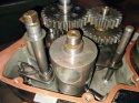
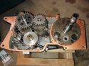
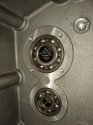
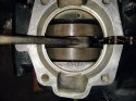
I'm working on a 74 400 Cross. Have disassembled the engine, replaced bearings & inspected everything. Working on buttoning it back up but running into problems. I'm using a Tusk case assembly tool and have installed the crank into the left half, and the transmission. Pretty sure I have everything in it's proper place, before attempting to install right case I went through all of the gears & it looks to be working OK.

Manual says to use a plastic or rubber mallet to tap the back part of the cases together as the case is pulled into place in the front. This worked for a bit but now it is binding and does not want to move so I've stopped for now. Case half's are still about 8mm apart.

This is my 2nd attempt. Last time I used the Allen head bolts to force the back part of the case to move. It got pretty tight towards the last and I was afraid I might break something. I did get the case halves to come together but when I removed the Tusk tool the crank did not want to spin. If I loosed the Allen bolts the crank would spin but a gap appeared between the cases so I took it apart again.

This is not my first engine rebuild. I've done a couple of Hondas and a bunch of Bultacos but this is my first Husky. Never had this kind of problem before.

So my questions are:

-Is it safe to use the Allen screws to bring the back part of the case together? If something is misaligned, forcing it could break the case but since I already got it together once I think that indicates that I do not have that problem.

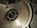
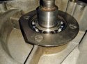
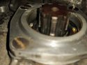
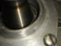
-So why is it so difficult getting the cases to come together? I did try to do it quickly after removing the right case from the oven while it was still hot after installing the bearings but by the time I got the Tusk tool on things were already cooling down. There are no noticeable nicks or imperfections on the crank or sprocket spline to prevent the bearings from going on smoothly.

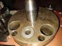
-I'm wondering if it's possible that I did not get the crank far enough into the left case half and could that be part of the reason it's binding? I do not see a specification anywhere showing how much clearance should be between the crank and the case. Is there a way I could measure to see if it's close enough or not? Maybe by trying to force the right side I'm working on the wrong problem?

Any help would be appreciated. There is a shop that works on vintage Huskys but it's 80 miles away so I'd rather solve this without the 160 mile drive.
 
DFA, Thanks for the reply! I took a quick look at your previous thread. Will look at the whole thing when I have more time. Damn! That's a nice looking crank tool you're using!

My left side bearing is up against the plate but maybe I didn't pull the crank far enough into it. I'm gonna see if I can move the crank further to the left. Also will check out one of my Bultaco motors & see how much clearance it has.

Yeah, I knew I was doing wrong when I forced it last time. I feel lucky I didn't have a disaster and I don't have the nerve to try it again. If I don't have success with this I guess I'll do the long drive to the Husky guy. It's not just the 160 mile round trip but it's almost certain that he'll keep it for a while, meaning at least 2 trips.
 
And we really need pics so we can see what your seeing, might se something you don't. Lots of pics!! Also when you get the crank in the left case measure from the case edge to center of the crank and that will tell you if you are seated or not into the left case. Look for marks on the crank when you pull it back apart to determine witch case it touching. Post 126, in my thread shows the tell tail marks of a rubbing crank. Chris
 
I've had this problem on this series engine. The problem on my project was the counter shaft wouldn't slide all the way into the bearing. Like yours, the cases would go together until about a 1/4". I surmised that the counter shaft had a defect I couldn't see so I used a piece of 2000 grit wet/dry and lightly went around the shaft. Slid together after that. With the tight clearances the shafts have on the bearings I don't think it takes much to create a problem, possibly even stuff the naked eye can't see. On my projects if there are any drag marks on any of the shafts I take the wet/dry to them, not to eliminate the marks but rather just get the high defects down to the proper diameter of the shaft. Be careful of any seal surface, the smallest scratches can effect the seals performance.

Crankshaft to case clearance is about 2mm on each side. The seal hub on the left side of the crank should just be touching the bearing race and the thrust washer on the right side just touching the right bearing race.

Transmission can be in any gear when assembling.
 
I will take some pictures & post tomorrow. I stuck a feeler gauge between the left crank side & case. It measured 134 thousandths, about 3.5 mm. Tried to draw it up and got it to just over 2mm but then when I released the tool it went back to about 99 thousandths. 2mm would be about 79 so it's still not right.

I removed the right side case and called it a night. At this point I might just pull the crank out of the left side and put it back on my truing jig to make sure I haven't distorted it with all my monkeying around.

Crash, I'm pretty sure it's the crank that's holding things up, not the CS shaft. Maybe I'll take some 2000 grit and give it a once over, though with metal that hard and sandpaper that fine I doubt it will make any difference.

DFA, for reference I'm using a .pdf manual I found online, called 'Husqvarna All 2-Stroke Repair and Clymer Vintage Dirt Bikes manual with Husqvarna included. Neither mentions putting transmission in any specific gear, though both leave a lot to one's imagination.
 
Yup, the shafts are very hard and cleaning them up isn't meant to reduce there overall size but rather remove microscopic imperfections and burn on oil residue. I would also add that a drop of gear oil on the shafts doesn't hurt when assembling.

You mentioned that you could see that the left main bearing was up against the retainer plate, thats good, but are you certain the crank is sliding into the bearing 100%, or that the crank seal isn't goofing things up?

If it were me I'd pull the crank out of the right case and try and install it in the left without the transmission being a distraction and see if slides all the way in the bearing. Measure the length of the left crank stub and subtract the width of the bearing and thats how much shaft should protrude from the bearing when the crank is installed. This way you'll know if the crank is getting held up or if its something else.


Since the distance between the crank and left side case is above 2mm I think it probably is not all the way in. I am planning to remove it and try again. I will use your process for measuring and a little oil couldn't hurt. Not sure I want to remove the tranny though... Took me a long time to get that in and feeling like I had it correct. Not sure how the interior crank seal could be interfering. It would pretty much have to be shredded. I wouldn't like that!
 
Some pictures of what I have. Right side case is removed. Crank & tranny still in left side.
 

Attachments

  • Husky1.jpg
    Husky1.jpg
    137.8 KB · Views: 21
  • Husky2.jpg
    Husky2.jpg
    150.7 KB · Views: 18
  • Husky3.jpg
    Husky3.jpg
    165.3 KB · Views: 71
  • Husky4.jpg
    Husky4.jpg
    155.7 KB · Views: 17
Only lets me post 4 files...
 

Attachments

  • Husky5.jpg
    Husky5.jpg
    128.7 KB · Views: 13
  • Husky6.jpg
    Husky6.jpg
    185.8 KB · Views: 10
  • Husky7.jpg
    Husky7.jpg
    156.7 KB · Views: 12
  • Husky8.jpg
    Husky8.jpg
    109.8 KB · Views: 12
It looks like maybe the rear or farthest to the rear shift fork shaft was hanging up on the left side case. Looks like there is a bure on the case hole the shift shaft fork goes into. Sometimes as you start getting close to the cases coming together you have to jiggle the left case a bit to get the shift shafts to drop in or line up with the holes. You can also polish the end of the shift fork shafts to help make it easier for them to slide into the left side case holes.

Marty

Sorry I meant to say right side case.
 
Hey Marty,

I think you must mean the right side case since my pictures have the crank & trans in the left side.

Yes, good eye! I did have a small chip in the right side case. Guess I can try to polish it and maybe clean up the receiving hole.
 
The seal collar on the countershaft goes on after the cases are assembled but you probably know that.
husky3-jpg.104467
 
From this view the space between the left side of the crank and the case is definitely to big so there is either something keeping the crank stub from sliding into the bearing or the seal is getting held up at seal journal. Wonder whats keeping the right side from sliding on?

husky10-jpg.104474
 
Back
Top