• 2 Stroke Husqvarna Motorcycles Made In Italy - About 1989 to 2014
    WR = 2st Enduro & CR = 2st Cross

  • Hi everyone,

    As you all know, Coffee (Dean) passed away a couple of years ago. I am Dean's ex-wife's husband and happen to have spent my career in tech. Over the years, I occasionally helped Dean with various tech issues.

    When he passed, I worked with his kids to gather the necessary credentials to keep this site running. Since then (and for however long they worked with Coffee), Woodschick and Dirtdame have been maintaining the site and covering the costs. Without their hard work and financial support, CafeHusky would have been lost.

    Over the past couple of weeks, I’ve been working to migrate the site to a free cloud compute instance so that Woodschick and Dirtdame no longer have to fund it. At the same time, I’ve updated the site to a current version of XenForo (the discussion software it runs on). The previous version was outdated and no longer supported.

    Unfortunately, the new software version doesn’t support importing the old site’s styles, so for now, you’ll see the XenForo default style. This may change over time.

    Coffee didn’t document the work he did on the site, so I’ve been digging through the old setup to understand how everything was running. There may still be things I’ve missed. One known issue is that email functionality is not yet working on the new site, but I hope to resolve this over time.

    Thanks for your patience and support!

125-200cc 144 kit PV's

justplayin

Husqvarna
AA Class
OK,
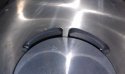
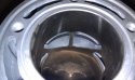
Got my 144 kit and have some questions for you experts out there. I have read about wrong valves, 2 of the same side valves, hand filing/fitting valves......so while I'm waiting for my .4 base gasket I figured I'd ask. I know for sure that I have a left and a right valve. I am also pretty confident that I have 144 valves and not 125 valves (from what I read they are different). My questions are:

1. Am I correct about the valves?
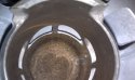
2. To me it looks like the right valve is closer to the piston than left? (3rd pic cyl is upside down) Does it matter that much?
3. Is there a certain clearance you want between the PV face and the piston? What is it?
4. If I need to bring the valve closer, do I file the valve where it hits the stop in the cyl?
5. Is there any special "mod" (that anyone would care to share) I can/should do to the PV before I assemble?

I do have mechanical knowledge and the tools to work with so technical terms are not a problem for me.
Thanks,
 

Attachments

  • 144.jpg
    144.jpg
    75.9 KB · Views: 35
  • vic pv3.jpg
    vic pv3.jpg
    92.6 KB · Views: 38
  • vic pv2.jpg
    vic pv2.jpg
    98.2 KB · Views: 31
I just put a new ring in mine last night and measured the PV clearance. 2.5mm on the left and about 2mm on the right. I don't know if that is normal but it seems a bit much.
 
Do you have the linkages installed or did you just drop the valves in the slot without reassembling the shaft and spacers?
 
Do you have the linkages installed or did you just drop the valves in the slot without reassembling the shaft and spacers?
I just slid the valves in the cyl. on the bench. Upon further inspection, I noticed that the right "closer" PV hits the stop on the outside of the PV in the cyl BUT the left valve actually hits the inside (center of cyl) and it does not contact the outside stop at all. After looking closely at the center rib you can clearly see a machining difference on them. I will try to get a pic.
 
Don't panic yet, mine did the same thing. When you install the shaft and spacers and bolt everything back together, I think you'll see a much better alignment... I did.
 
Don't panic yet, mine did the same thing. When you install the shaft and spacers and bolt everything back together, I think you'll see a much better alignment... I did.
Well I can't get a pic but I think you guy's know what I mean. Actually, now that I know what I'm looking for, I can clearly see it in the pics I posted. If you look at the first pic, you can see where the left valve is stopping short of the outer stop.
I didn't think that I would have to have everything assembled. I mean, with the coil spring on the PV shaft that takes up the "over" movement of the PV linkage, I thought that the PV's would "have" to be on the stop when fully closed. If not, why have the spring? (well, I know "why" it's there but I think you know what I mean)
 
Well I can't get a pic but I think you guy's know what I mean. Actually, now that I know what I'm looking for, I can clearly see it in the pics I posted. If you look at the first pic, you can see where the left valve is stopping short of the outer stop.
I didn't think that I would have to have everything assembled. I mean, with the coil spring on the PV shaft that takes up the "over" movement of the PV linkage, I thought that the PV's would "have" to be on the stop when fully closed. If not, why have the spring?
Just got finished installing the kit on Monday. I did the exact same thing as you did, with the same result, and reached the same incorrect (in my case) conclusion. When you install the linkage hardware (shaft, spacers, plates) and bolt them all up, you'll see what I mean. The milling "stops" in the ports are not designed to be seats (or stops) for the valves. When you get the shaft and spacers and plates installed, it will pull the valves up in the ports so they don't even touch the milled-out ridges. When it is all assembled, the actual travel "stop" for the valves is the spacers hitting the plates. Try it.
 
Just got finished installing the kit on Monday. I did the exact same thing as you did, with the same result, and reached the same incorrect (in my case) conclusion. When you install the linkage hardware (shaft, spacers, plates) and bolt them all up, you'll see what I mean. The milling "stops" in the ports are not designed to be seats (or stops) for the valves. When you get the shaft and spacers and plates installed, it will pull the valves up in the ports so they don't even touch the milled-out ridges. When it is all assembled, the actual travel "stop" for the valves is the spacers hitting the plates. Try it.

Cool, when I go to put it together I'll look at it then. See, that's what great about this place, if you run into a problem or question someone has already been there.
Thanks:cheers:
 
Cool, when I go to put it together I'll look at it then. See, that's what great about this place, if you run into a problem or question someone has already been there.
Thanks:cheers:
I'm pretty sure your result will be the same as mine. When I looked at your pics, my first thought was... "Oh man, that looks exactly like what I saw when I was "dry fitting" my valves". I was ready to send my kit back to the dealer! Then I thought: "What the hell, let me at least assemble the guts and see what it looks like". In my case, it all turned out good. Engine started in 3 kicks and after 3 heat cycles, it's pulling like my '11 CR 150!

Hopefully, you'll have the same outcome (pretty sure you will)... Good luck! :thumbsup::cheers:
 
Back
Top