run-it
Husqvarna
AA Class
Hey guys, the other day I found this really good place to power up your stuff so I wanted to get the word out. It's switched too, so when you turn the key off yer grip warmers, gps, radar detector, whatever will shut off. I'm cross-posted from ADV.
1) First, remove the four shinny screws that secure the panel above the headlight.
2) Now look at the bottom of your ignition switch, follow the larger of the two cables to inside the headlight housing. You'll come to this connector...
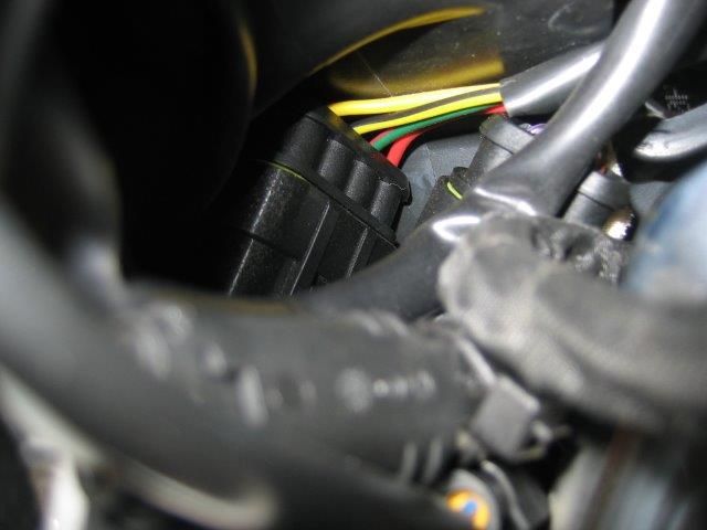
Keep following to the front side which looks like this...
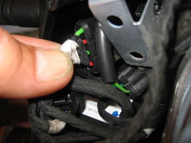
3) See the two green wires? Tap into either or both to run your stuff.
Just undo the tape to expose the wire & tap in with a solder connection, install an inline fuse/holder & go. You'll have to find a convenient place for ground, I'd suggest the downtube frame nuts/bolts just behind the radiator or run a single wire back to the neg side of the battery.
Now for sme detail about this circuit - You don't need to understand the following jibberish so just ignore if it doesn't make sense to you...
How much of a load will this circuit handle?
I don't exactly know but it's a heavy circuit, they look like (edit)14AWG 16AWG wires, if so using both of the wires would be good for a total of 50 44A or 600 528W so no problem there, we are limited by the 30A fuse they originate from. I'm sure there's ample reserve for what I'm doing, heated grips & electronics.
Those wires originate & terminate joined together, I imagine they simply used a pair for redundancy & flexibility. Said another way, both those green wires are the same. They are not two different circuits. Tap into both to get maximum current capability. Said another way, tap into both green wires then join those wires together, now run that into a fuse, now run to your stuff.
Heated items like grips & vests use the most current. Typical heated grips use 40W / 3.3A. Electronics practically use zilch. If you're just running electronics either single green wire will do.
Where does this circuit originate?
From the starter relay, it goes through the 30A fuse there.
Where does this circuit go?
It feeds part of the fuse block, F1 (7.5A), F2 (15A), F7 (4A). For more specifics see the list of items on the wiring diagram.
Disclaimer - I'm going off the bike's wiring schematic, I haven't done anything with the circuit yet but plan to. Just wanted to get the word out so people can keep their life simple & bikes uncluttered with relays & wiring. Thanks RidingDonkeys for the wiring diagram.

1) First, remove the four shinny screws that secure the panel above the headlight.
2) Now look at the bottom of your ignition switch, follow the larger of the two cables to inside the headlight housing. You'll come to this connector...

Keep following to the front side which looks like this...

3) See the two green wires? Tap into either or both to run your stuff.
Just undo the tape to expose the wire & tap in with a solder connection, install an inline fuse/holder & go. You'll have to find a convenient place for ground, I'd suggest the downtube frame nuts/bolts just behind the radiator or run a single wire back to the neg side of the battery.
Now for sme detail about this circuit - You don't need to understand the following jibberish so just ignore if it doesn't make sense to you...
How much of a load will this circuit handle?
I don't exactly know but it's a heavy circuit, they look like (edit)
Those wires originate & terminate joined together, I imagine they simply used a pair for redundancy & flexibility. Said another way, both those green wires are the same. They are not two different circuits. Tap into both to get maximum current capability. Said another way, tap into both green wires then join those wires together, now run that into a fuse, now run to your stuff.
Heated items like grips & vests use the most current. Typical heated grips use 40W / 3.3A. Electronics practically use zilch. If you're just running electronics either single green wire will do.
Where does this circuit originate?
From the starter relay, it goes through the 30A fuse there.
Where does this circuit go?
It feeds part of the fuse block, F1 (7.5A), F2 (15A), F7 (4A). For more specifics see the list of items on the wiring diagram.
Disclaimer - I'm going off the bike's wiring schematic, I haven't done anything with the circuit yet but plan to. Just wanted to get the word out so people can keep their life simple & bikes uncluttered with relays & wiring. Thanks RidingDonkeys for the wiring diagram.