DeathFromAbove
My Cat Says AREAR!
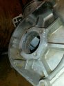
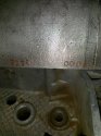
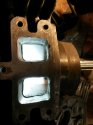
Hi and Merry Christmas to all. This is my first thread, please bear with me.. I have 2 1972 450 engines. The first I think is a WR with a 6 speed trans, engine number is 2120 0008 on the center case seam. I bought it out of Lancaster PA. It was in a 360rt frame and had a cut head for I think a 400 pipe. Everything on the bike is pretty crappy! When I pulled it apart, the usual, flywheel stub thread gone, stub drilled off center and standard 3/8 16. Bearings smoked, rod, big and little bearing surfaces NG.
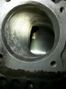
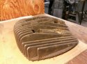
  The rig is worn to 3mm gap. Must I go on?? Oh the cylinder is 86.94mm top and 84.10mm bottom, the ports have been ground on the head and don't really match the cylinder.OK, I've got a couple of serviceable cranks, bought a std piston and head(ebay), a std ring, stub, bearings, seals and gaskets (Thanks John@Vintage Husky). I'm looking for a diagram of or any info on the switch from 5 to 6 speed, so I can make sure it's assembled correctly. The cases were plenty porous, a lot of welding was done but they look good for being early. I have most of the # for the trans parts but have no idea what they are from, any help would be great. Thanks Here's some pics.
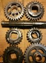
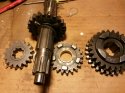
This is my first thread, please bear with me.. I have 2 1972 450 engines. The first I think is a WR with a 6 speed trans, engine number is 2120 0008 on the center case seam. I bought it out of Lancaster PA. It was in a 360rt frame and had a cut head for I think a 400 pipe. Everything on the bike is pretty crappy! When I pulled it apart, the usual, flywheel stub thread gone, stub drilled off center and standard 3/8 16. Bearings smoked, rod, big and little bearing surfaces NG. The rig is worn to 3mm gap. Must I go on?? Oh the cylinder is 86.94mm top and 84.10mm bottom, the ports have been ground on the head and don't really match the cylinder.OK, I've got a couple of serviceable cranks, bought a std piston and head(ebay), a std ring, stub, bearings, seals and gaskets (Thanks John@Vintage Husky). I'm looking for a diagram of or any info on the switch from 5 to 6 speed, so I can make sure it's assembled correctly. The cases were plenty porous, a lot of welding was done but they look good for being early. I have most of the # for the trans parts but have no idea what they are from, any help would be great. Thanks Here's some pics.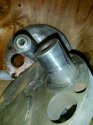


.jpg")

